ORDER NO. 119106
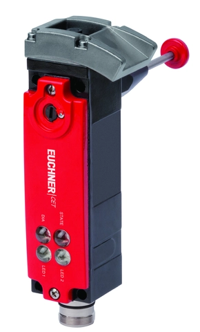
Non-contact safety switch CET-AP-…, with plug connector RC18 and escape release
- Read head with guard locking and integrated evaluation electronics
- Locking force up to 6,500 N
- Short circuit monitoring
- 2 safety outputs (semiconductor outputs)
- Category 4 / PL e according to EN ISO 13849-1
- Plug connector M23 (RC18)
- Unicode
- Door monitoring output
- Indication of the door position by LED
- Teach-in input
- Escape release, 105 mm long
- Approach direction A (delivery state)
Approach direction
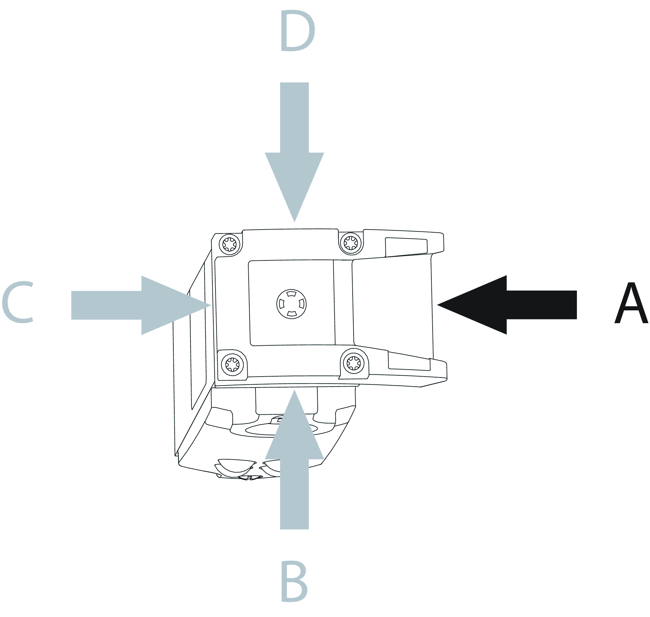
Horizontal
Can be adjusted in 90° steps
Safety switch
The device may be operated only in conjunction with the actuator CET-A-…
Important: The actuator must be ordered separately.
Unicode evaluation
Each actuator is highly coded (unicode). The switch detects only taught-in actuators. Additional actuators can be taught-in. Only the last actuator taught-in is detected.
Solenoid operating voltage
- DC 24 V 10%, -15%
Guard locking type
| CET3 | Closed-circuit current principle, guard locking by spring force. Release by applying voltage to the guard locking solenoid. The door position is also monitored. The door monitoring output OUT D is set to HIGH as soon as the actuator is above the extended plunger (state: door closed, guard locking not active). The output OUT D also remains set when guard locking is active. |
LED function display
| State LED | Status LED |
| DIA LED | Diagnostics LED |
| LED 1 rd | illuminates when the solenoid is energized |
| LED 2 gn | illuminates when the door is closed |
Additional connections
| OUT | Monitoring output (semiconductor) |
| OUT D | Door monitoring output |
| RST | Reset input |
| J | Teach-in input |
Category according to EN ISO 13849-1
Due to two redundantly designed semiconductor outputs (safety outputs) with internal monitoring suitable for:
- Category 4/PL e according to EN ISO 13849-1
- The stated safety characteristics apply to any installation orientations of the safety switch.
Important: To achieve the stated category in accordance with EN ISO 13849-1, both safety outputs (OA and OB) must be evaluated.
Escape release
This is used for manual release of guard locking from the danger zone without tools.
Technical Data
Workspace
| Repeat accuracy R | |
| according to EN 60947-5-2 | 10 % |
Electrical connection values
| Fuse | |
| external (solenoid operating voltage UCM) | 0.5 … 8 A |
| external (operating voltage UB) | 0.25 … 8 A |
| Power consumption | |
| Solenoid | 11 W |
| Connecting cable | 30V DC, 2A |
| Operating voltage DC | |
| UB | 24 V DC -15% … +15% reverse polarity protected, regulated, residual ripple < 5%, PELV |
| LED | 24 V DC -15% V DC … +10% V DC |
| EMC protection requirements | according to EN IEC 60947-5-3 |
| Utilization category | |
| DC-13 | 24V 200mA |
| Solenoid operating voltage DC | |
| UCM | 24 V DC -15% … +10% reverse polarity protected, regulated, residual ripple < 5%, PELV |
| Solenoid duty cycle | 100 % |
| Switching load | |
| according to UL | 24V DC, Class 2 |
| Safety class | |
| EN IEC 61140 | III |
| Current consumption | |
| ICM | 450 mA |
| IB | 80 mA |
| Test pulse duration | max. 0.3 ms |
| Degree of contamination (external | 3 |
| Teach-in input | |
| Input voltage | |
| LOW | 0 … 1 V DC |
| HIGH | 15 … 27.6 V DC |
| Monitoring output OUT D | |
| Output type | p-switching, short circuit-proof |
| Output voltage | |
| OUT D | 0.8xUB … UB V DC |
| Switching current | |
| OUT D | 1 … 50 mA |
| Switching delay from state change | max. 700 ms |
| Monitoring output OUT | |
| Output type | p-switching, short circuit-proof |
| Output voltage | |
| OUT | 0.8xUB … UB V DC |
| Switching current | |
| OUT | 1 … 50 mA |
| Switching delay from state change | max. 400 ms |
| Safety outputs OA / OB | |
| Output type | 2 semiconductor outputs, p-switching, short circuit-proof |
| Output voltage | |
| HIGH U(OA,OB) | UB-1.5V … UB V DC |
| LOW U(OA,OB) | 0 … 1 V DC |
| Discrepancy time | |
| both safety outputs | max. 10 ms |
| Turn-on time | 400 ms |
| Off-state current Ir | max. 0.25 mA |
| Risk time according to EN 60947-5-3 | |
| Single device | max. 400 ms |
| Switching current | |
| per safety output OA / OB | 1 … 200 mA |
Mechanical values and environment
| Approach speed | max. 20 m/min |
| Connection type | 1 plug connector M23, 19-pin, RC18 |
| Ready delay | 1 s |
| Installation orientation | any |
| Switching frequency | max. 0.5 Hz |
| Degree of freedom X | ±5 mm |
| Degree of freedom Y | ±5 mm |
| Degree of freedom Z | ±4 mm |
| Mechanical life | 2 x 10⁶ |
| Shock and vibration resistance | according to EN IEC 60947-5-3 |
| Degree of protection | IP65/IP67 |
| Ambient temperature | |
| at UB = 24V DC | -20 … +55 °C |
| Material | |
| Ramp | stainless steel |
| Safety switch housing | Die-cast aluminum |
| Locking force Fmax | 6500 N |
| Locking force FZh | 5000 N |
| Guard locking principle | Closed-circuit current principle |
Characteristic values according to EN ISO 13849-1 and EN IEC 62061
| Mission time | 20 y |
| Control of guard locking | |
| Category | Depending on external control of guard locking |
| Performance Level | Depending on external control of guard locking |
| PFHD | Depending on external control of guard locking |
| Monitoring of guard locking and the guard position | |
| Category | |
| Any installation orientation | 4 |
| Performance Level | PL e |
| PFHD | |
| Any installation orientation | 3.1 x 10⁻⁹ |
Miscellaneous
| C number | |
| C2312 | extended escape release |
| The following applies to the approval according to UL | Operation only with UL Class 2 power supply or equivalent measures; see operating instructions |